
Encoder Simulator DSD-ESM-1945
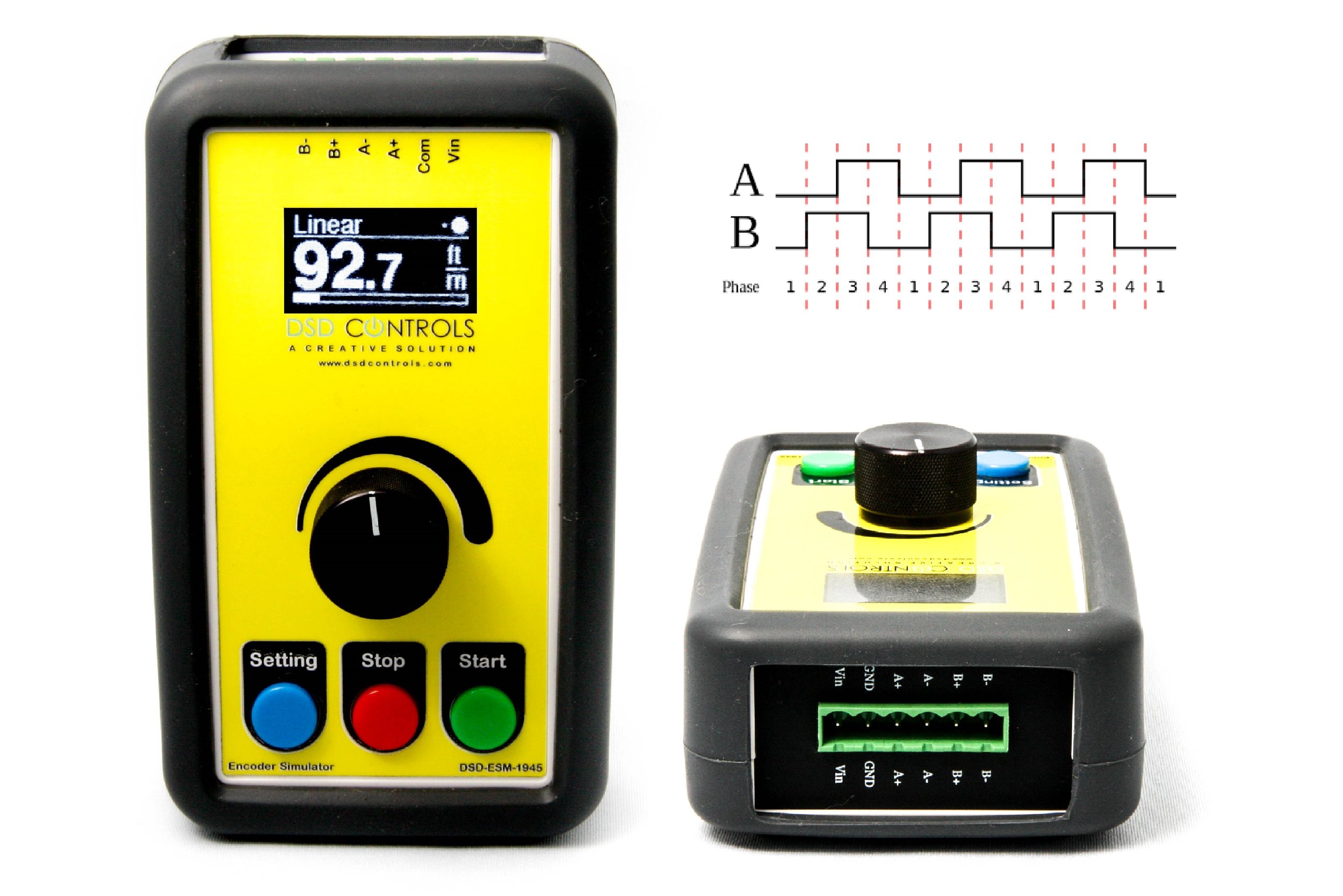
Encoders have been used in many different applications to track the speed and position of a motor shaft or tracking the moving material. The encoder simulator generates voltage pulses that simulate the function of a quadrature pulse encoder having A+/A- and B+/B- channels. The digital waveform that is created represents an encoder that is rotating at a given speed.
The encoder simulator is used when performing a dry run of a machine in "auto mode" without having to use any material. In such a case, the machine depends on a constant flow of voltage pulses from a material encoder, and these pulses can be created by the encoder simulator.
The DSD-ESM-1945 has 3 different operating mode to simulates the encoder pulses in various applications: Linear, Rotary & Frequency.
Linear Mode is to simulate the encoder which is tracking the moving material
Rotary Mode is to simulate the encoder which is tracking a rotating shaft
Frequency Mode is to simply generate quadrature pulses at given rate
The encoder simulator accepts several user inputs that are required to generate the waveform, such as:
1. Line speed.
2. Direction.
3. PPR (Pulse Per Revolution, desired number of pulses per revolution of the encoder)
4. Encoder wheel circumference
5. Standard of measurement (Metric or Imperial)
For example, to simulate the motion of a sheet of steel moving at 100 feet per minute using a 1000 PPR encoder having a 12 inch wheel, the following inputs would be entered:
1. Standard of measurement = Imperial
2. Direction = forward
3. PPR = 1000
4. Wheel circumference = 12
5. Line speed = 100 ft/min
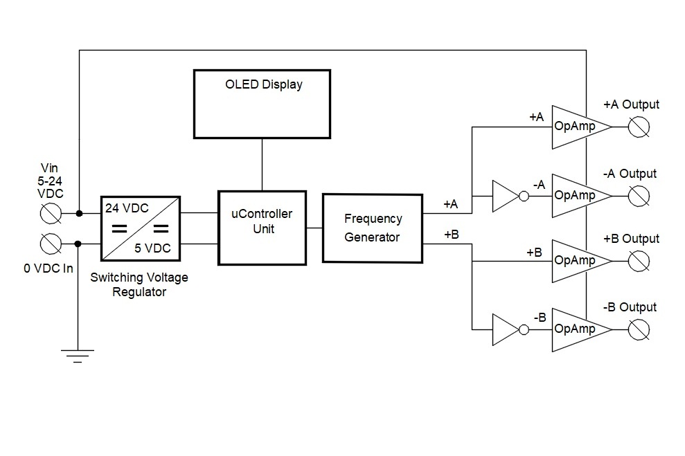
The simulator features an OLED display with a digitally encoded selection knob. The line speed can be adjusted while running by using the selection knob.
The user has to provide an external supply voltage from 5VDC up to 24VDC. The waveform amplitude will be the same as this voltage.
Before using the encoder simulator, the material encoder is temporarily disconnected from the electrical system and the encoder simulator is connected to the same terminals using a shielded twisted-pair cable. After using the simulator, it is disconnected from the electrical system and the material encoder is reconnected as before.